True, reliable protection for DC circuits
Miniature circuit breakers connected to 24 V DC often have difficulty in tripping, especially with long cable runs and small cable areas. Selectivity does not work and all groups drop out before the miniature circuit breaker trips in the thermal range, which can take several minutes.
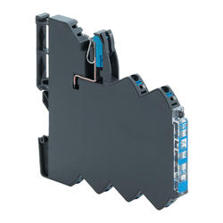
Lutze's LOCC Box range of electronic fuse trips reliably even with long cable runs, which provides good selectivity without power outages for fault-free groups. The fuse's rated current is set using a thumb-wheel under the safety cover. The current can be set between 1-10 A in 1 A steps.
NB: Change to rated current and characteristic can only be made when the fuse is in the disconnected position. LED turns red. If the rated current or characteristic is changed during operation, LED turns green so no change occurs. To change settings. Press the button at the front until the LED turns red (non-flashing). Change the value on the thumb-wheel and then restart using the button on the front.
Three different characteristics can be selected using a thumb-wheel:
- 1 : Fast blow,
- 2 : medium blow,
- 3 : slow blow,
- 4 : slow blow 2,
- 5 : slow blow 3.
Use the slow blow characteristics for connection of loads with high inrush current. Even if the slowest ranges are chosen, the fuse reacts very quickly to short circuits compared to miniature circuit breakers., that are only really designed for AC loads.
The 24 V DC connection can either be made directly to each fuse or using a power terminal block with a copper rail. This alternative is recommended if many fuses are to be installed beside one another. The fuse is connected to the rail using a sliding contact. Upon disconnection of the sliding contact, the fuse is galvanically isolated.
Resetting can either be conducted with a button on the front (the fuse can also be manually disconnected with the button) or via remote control. In the event of a tripped fuse, the LED flashes red. Once a fault is remedied, the fault is acknowledged with the button on the front or via remote control. The LED is then red, non- flashing. If many fuses are installed, it is easy to see which groups have been remedied. With a second reset signal, the fuse is activated and the LED shines green.
There is also a 24 V DC signal output (open collector) that falls when the fuse trips. The output can be connected into a group using strapping. If one of the fuses in the group trips, a signal is received. On model 716401, the signal output even falls with manual on and off.
(For more information about the lowest load resistances for the signal output, see the separate tab.)
The cover can be locked with a lead seal and marked with our RC55 marking; see the terminal rail chapter. The fuse has no galvanic isolation between input and output when it is connected to 24 V DC.
The LOCC Box is also available as a network version and can be combined with exisiting systems, operating with RS-232, CANopen, Profibus DP, Profinet IO or Ethercat protocols.
LOCC-Pads is free software that can be used with the LOCC Box-NET for programming your own parameters to match the load you are protecting, as well as a full anaysis & diagnostic tool for 12-24V dc circuits.
Please contact for a demonstration.
Signal output.
The signal output is of the open-collector type with pull-up resistors. With this design, groups can be combined and alarms triggered if one fuse in the group trips. Depending on the external load resistance, the output voltage for a non-tripped fuse can vary.
Example 1 . Only one fuse is used; the alarm output is connected to a PLC input of 10 kΩ. The output signal of the alarm output during operating status is 19.8 V DC. The alarm output's internal resistance is 2.1 kΩ. Re/Rtot * U = 10 kΩ/12.1 kΩ * 24 = 19.8 V)
Example 2 : 10 fuses are connected together into a group with a common alarm output to a PLC input of 10 kΩ. The output signal of the alarm output during operating status is 23.5 V DC. The alarm output's internal resistance is 2.1 kΩ. 2.1 kΩ/10 = 210 Ω. Re/Rtot * U = 10 kΩ/10.21 kΩ * 24 = 23.5 V DC.
If a relay coil that is often of low resistance is to be connected directly to the alarm output, +24 V DC must be connected directly to the relay; minus must be connected to the alarm output. NB: An inverted function is attained. When the fuse does not indicate a fault, the relay is not activated; relay activation occurs when there is a fault. We recommend our interface relays from Lutze, which have the same form factor as the fuse. Plug-in interface relays for outputs
If the MOSFET transistor that feeds the load fails for some reason during operation, the signal output will drop to zero. LED at the front will flash at very high rate and indicate a MOSFET transistor fault. If a short circuit occurs in conjunction with a MOSFET transistor fault, an internal fuse trips and disconnects the loads. With these integrated safety functions, a very safe system is attained even in the event of electronics failure.
A power terminal block manages 40 A. The 70 A rail. With connection of two power terminal blocks,
the entire rail's capacity of 70 A can be utilised. | |